

Gears, gear sets & gearboxes
Photographed gears, gear sets and gearboxes. Browse the samples by their visible structure.
Explore gears and gearboxes, busbar components, plastic bearing cages and other precision parts, including metal conductors and components with surface-processing requirements. Each category brings together product examples, photographs and available specifications. Share your drawing to define the tooling, molded-part, metal-component and surface-processing scope for your project.
Photographed gears, gear sets and gearboxes. Browse the samples by their visible structure.
Molded insulation, conductor interfaces and terminal components.
Cages for ball, needle-roller and segmented bearing arrangements.
Cooling parts, electronic housings and other precision components.
Product families: 62
Photographed gears, gear sets and gearboxes. Browse the samples by their visible structure.
Gearbox housings, mounting features and internal gear arrangements.
Gearbox samples with housings, mounting features and visible gear arrangements. Review part interfaces and the required assembly scope with your drawing.
View componentIndividual gear samples with tooth profiles, bores and inserts.
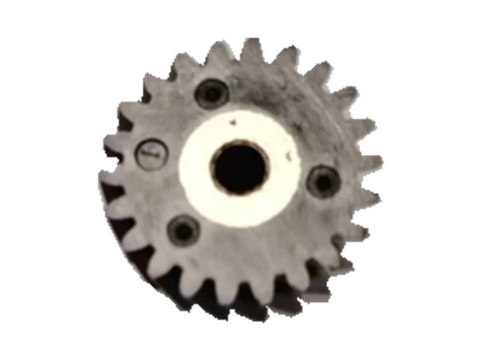
A gear sample with peripheral teeth and a central insert. Fit, material and tooling requirements follow the selected drawing.
View component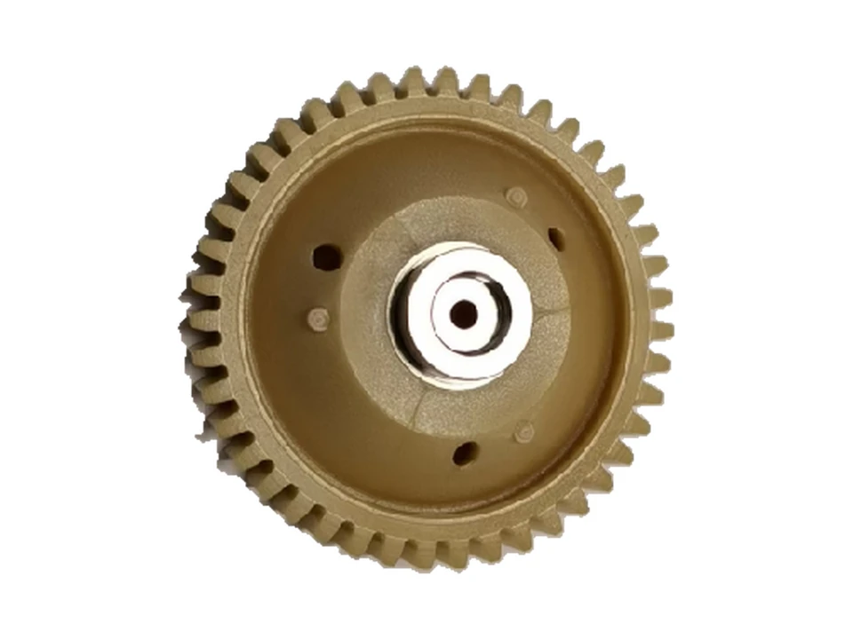
A gear sample with a toothed rim and central insert. Review the mounting interface and molding requirements for your version.
View component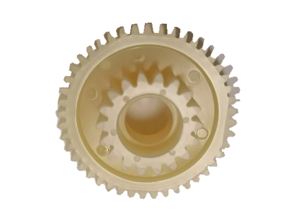
A compound gear sample showing the outer tooth profile and central connection structure. Gear geometry, material and interfaces are reviewed for each drawing.
View componentGear sets and their visible arrangement within the sample housing.
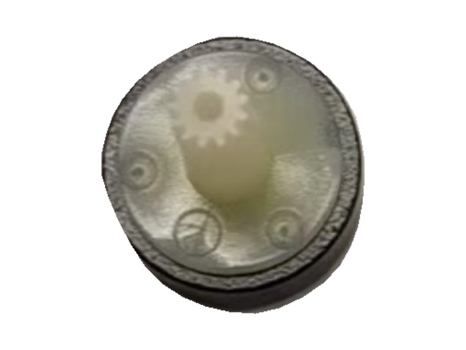
A photographed gear set inside a housing. The visible gear arrangement and central interface provide a reference for part and assembly discussions.
View componentMotor ring busbars, insulated connectors and their conductor components. Compare connection layouts and molded insulation structures.
Circular conductor and insulation layouts for motor connections, including pump and drone-motor examples.
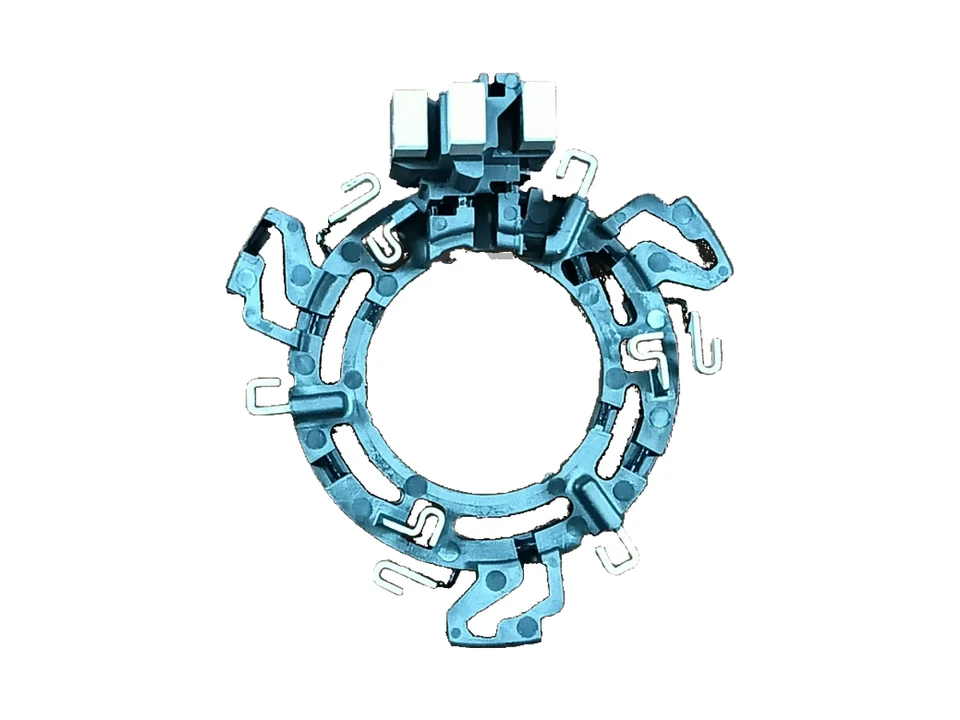
An insulated ring busbar with formed conductor terminals, a raised connection block and mounting arms. Terminal positions and the molded support are reviewed against the motor assembly drawing.
View component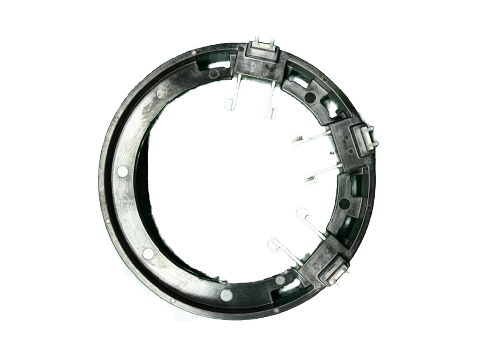
A cooling-pump motor busbar sample with conductor tabs arranged around a ring-shaped insulating support.
View component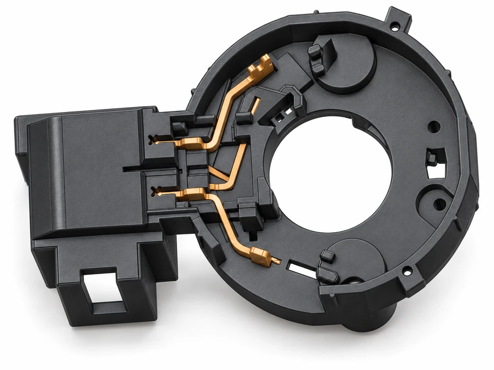
Product rendering
A ring-shaped connector design with conductor features in the support and a side socket for the mating connection.
View component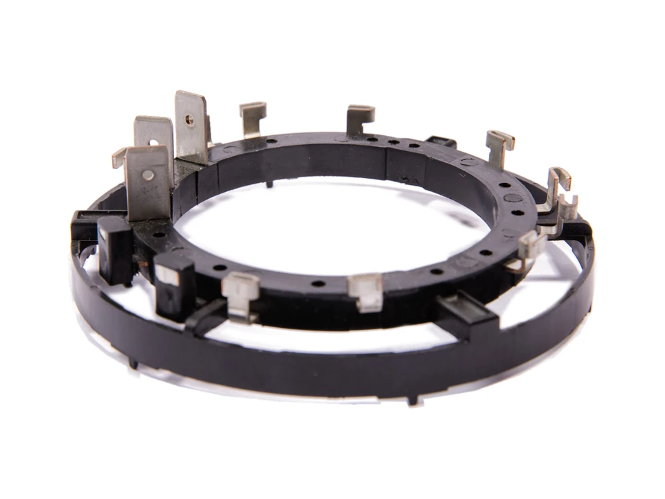
Motor busbar components with a circular insulating support and metal terminal connections, including a drone-motor sample.
Plate, strip and branched conductor layouts combined with molded insulation and connection interfaces.
Detail photograph
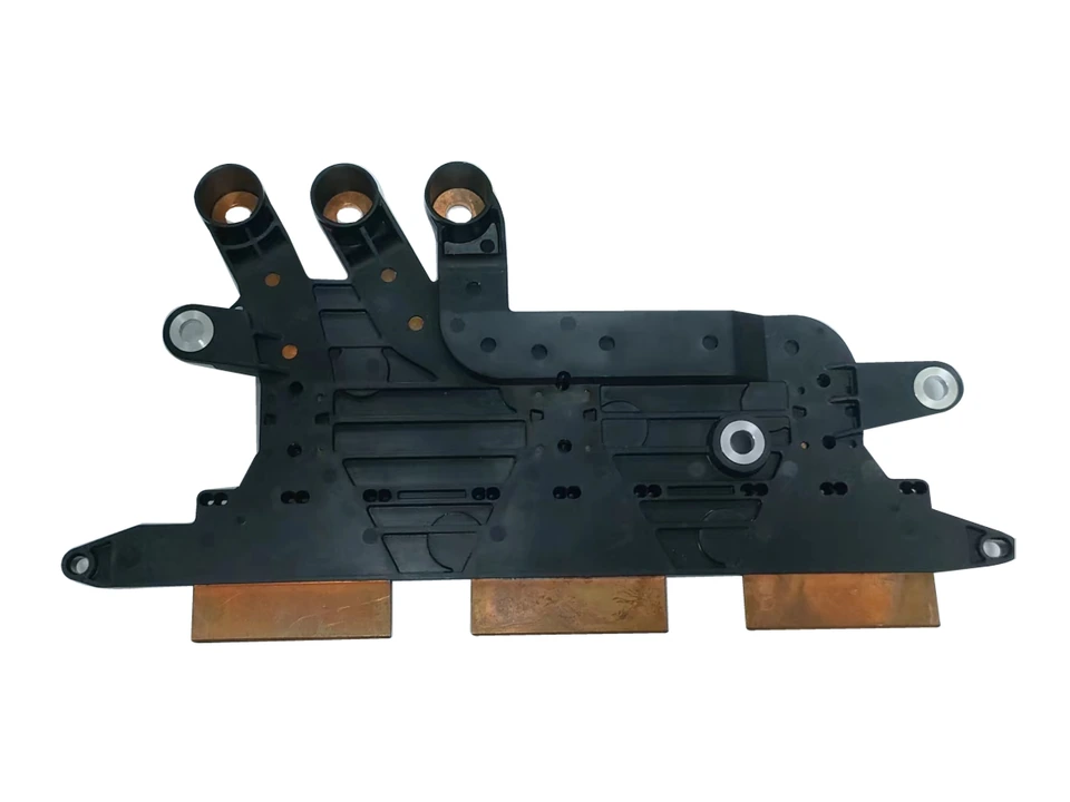
A plate-shaped busbar with three terminal sleeves, broad contact tabs and molded mounting features. Review conductor interfaces, fixing points and the insulation envelope for the intended assembly.
View component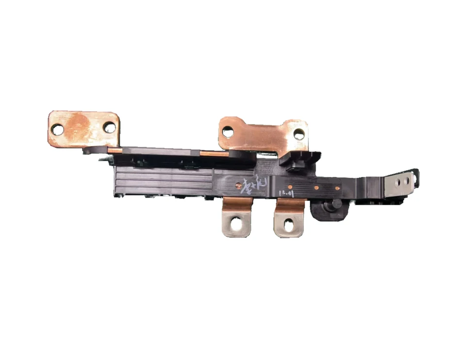
An elongated busbar with several conductor tabs arranged along a molded support.
View component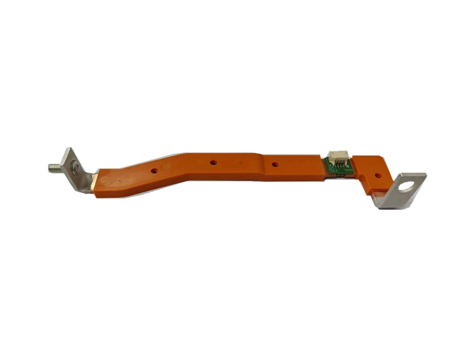
A strip-shaped conductor with molded insulation and exposed end connections for integration into a busbar assembly.
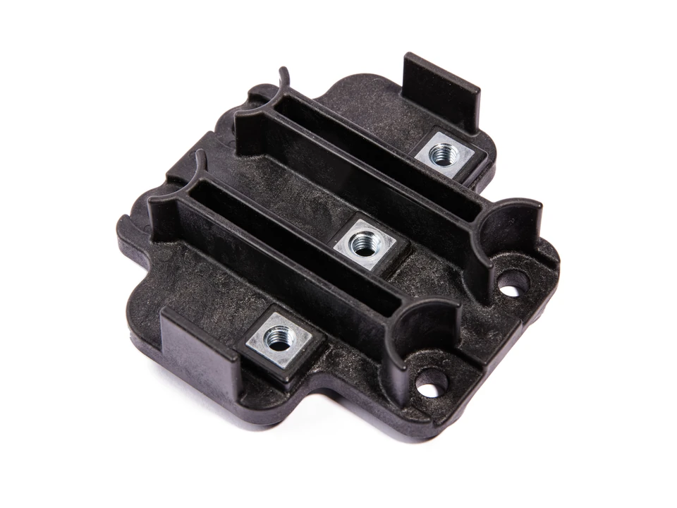
View componentAn EV busbar connector sample with three square threaded inserts separated by raised walls in the molded body.
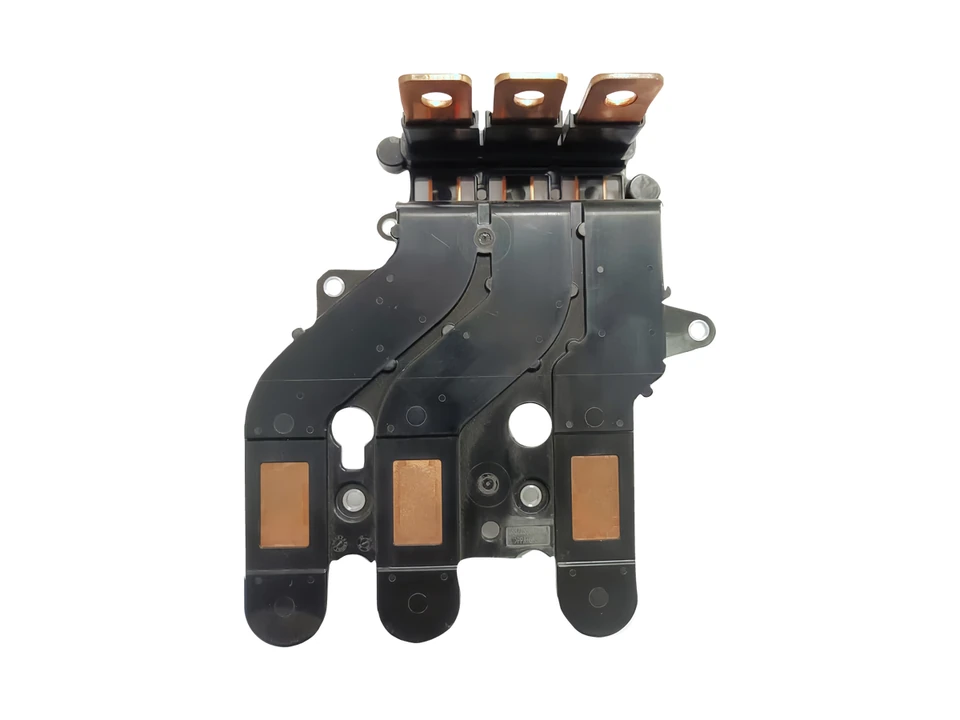
A three-branch automotive busbar connector combining conductor paths, molded insulation and mounting interfaces.
Metal connection components associated with busbar assemblies. Insert supply and manufacturing scope are agreed for each project.
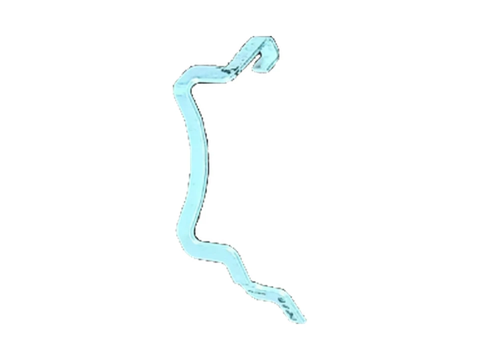
Formed conductors for busbar assemblies, with bends and terminal interfaces arranged around the installation space.
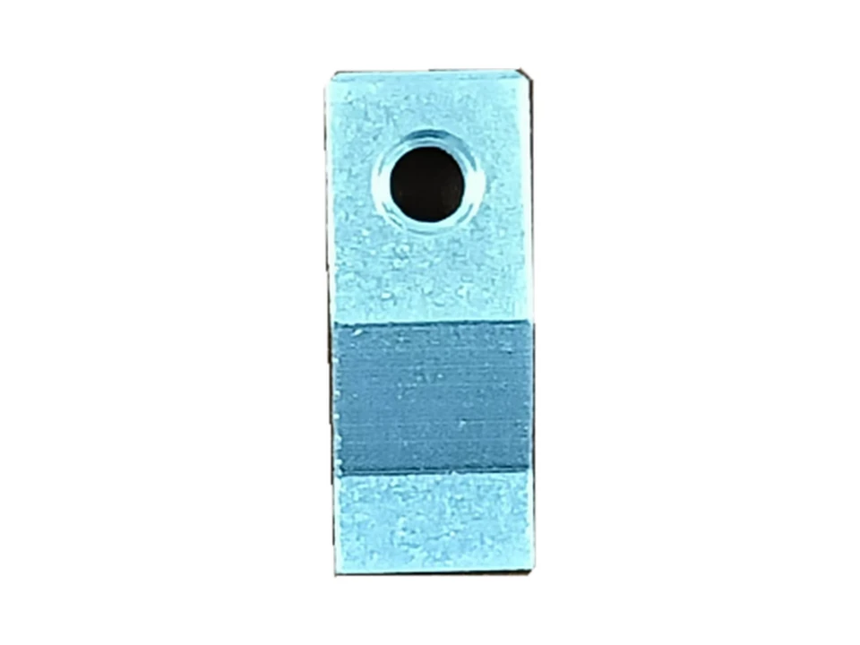
Thick busbar terminal components with connection holes and contact surfaces for the specified conductor interface.
View componentPress-fit terminal and carrier-strip examples, showing formed contact features and terminals retained in a strip arrangement.
Plastic cages for ball, needle roller and slewing bearing arrangements. Browse the pocket and frame structures used in each family.
Ball-bearing cages, including ring, crown and tubular structures and wheel-hub design examples.
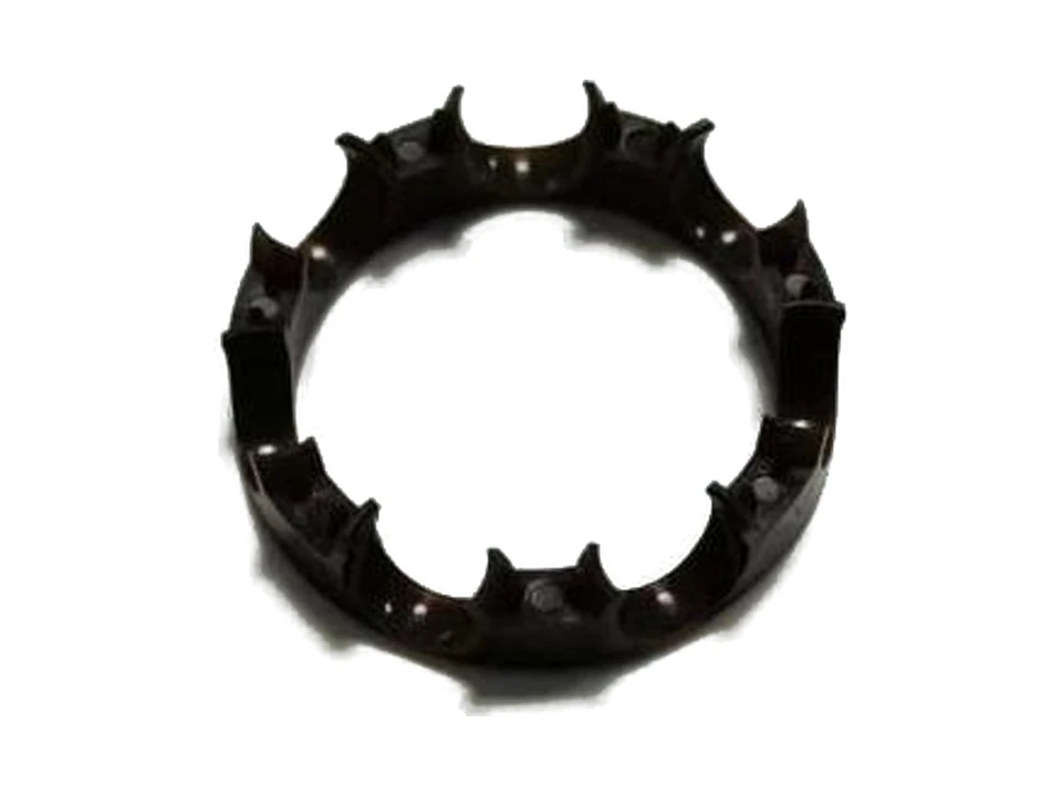
Plastic cages for deep-groove ball bearings, including ring and crown forms with pockets arranged around the circumference.
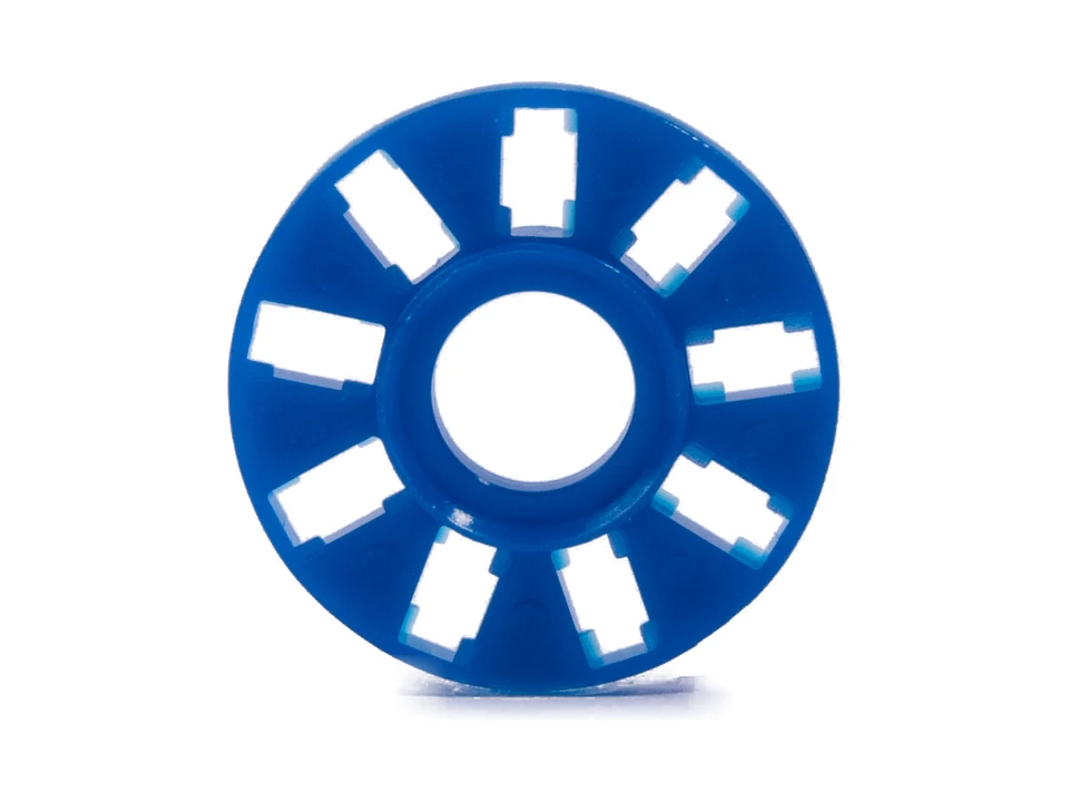
An annular plastic cage for thrust ball bearings, with ball pockets spaced around a central opening.
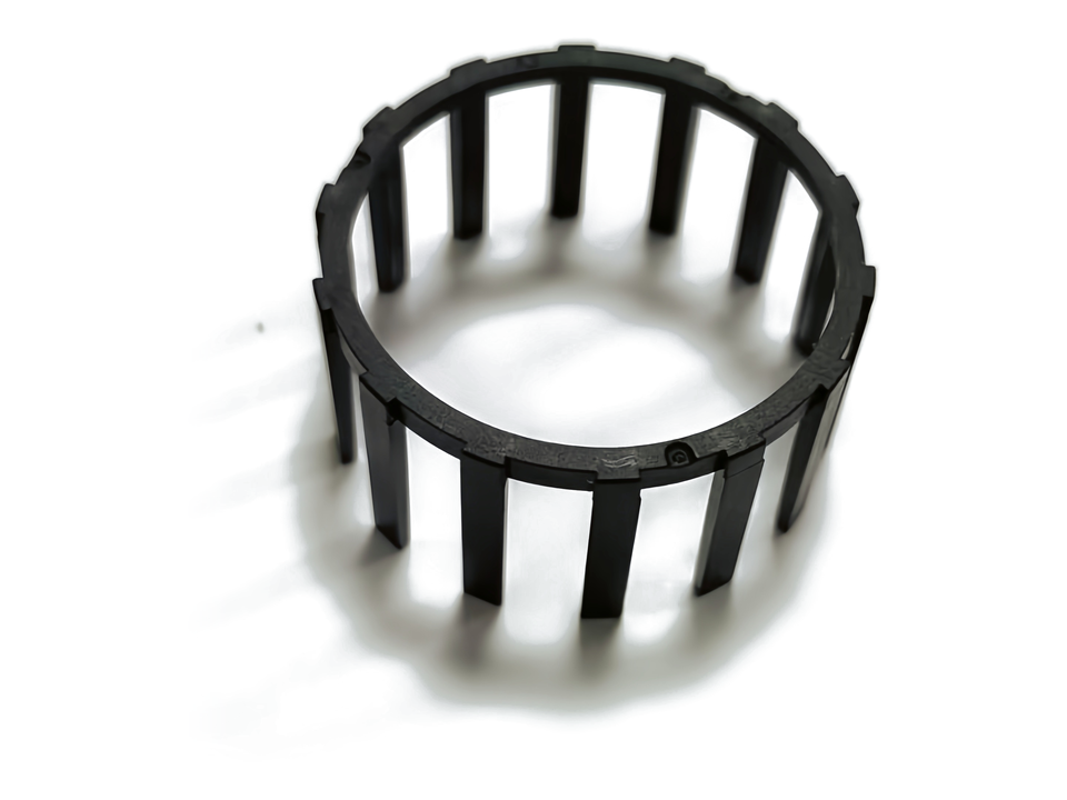
Ball-bearing cage structures with end rings and axial bars. Review the ball spacing, pocket shape and assembly envelope with the drawing when defining the mold and molded part.
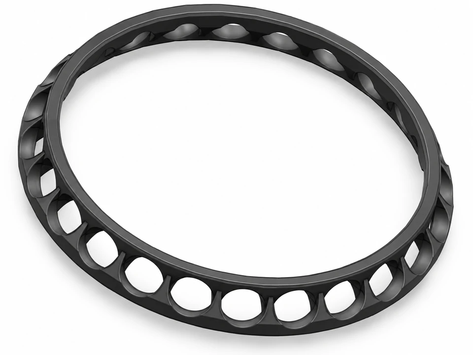
Product rendering
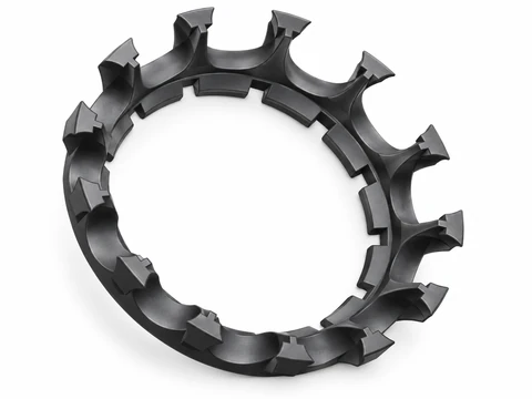 Open-pocket ring
Two ring-shaped cage designs show open and closed ball pockets for wheel-hub bearings. Compare pocket geometry, the ring profile and assembly clearances when defining your version.
View component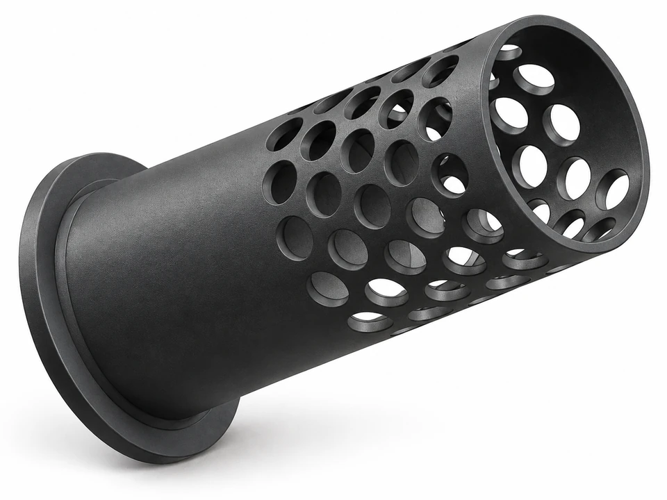
Product rendering
A tubular ball-bearing cage design with a flanged end and multiple rows of pockets. PPS is identified as the design material in the portfolio; grade, fit and operating requirements are specified for each project.
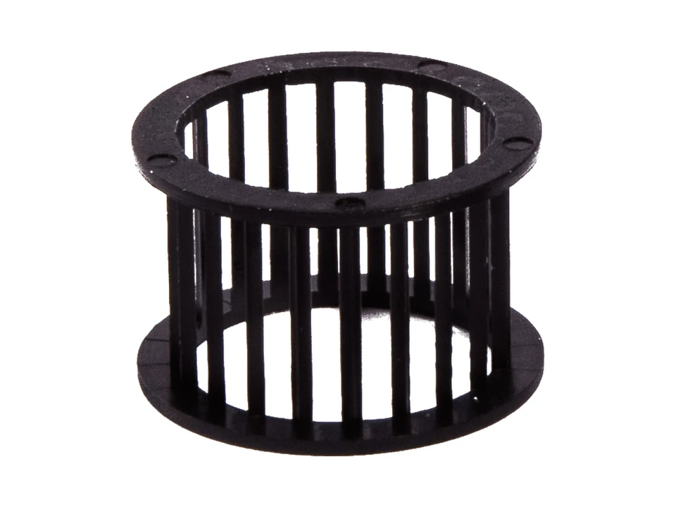
Cylindrical cages with axial bars and end rings that define the roller pockets.
Cylindrical plastic needle roller cages with slender axial bars and end rings forming the roller pockets.
View componentSegmented cage frames and individual separators for spacing rolling elements in slewing bearings.
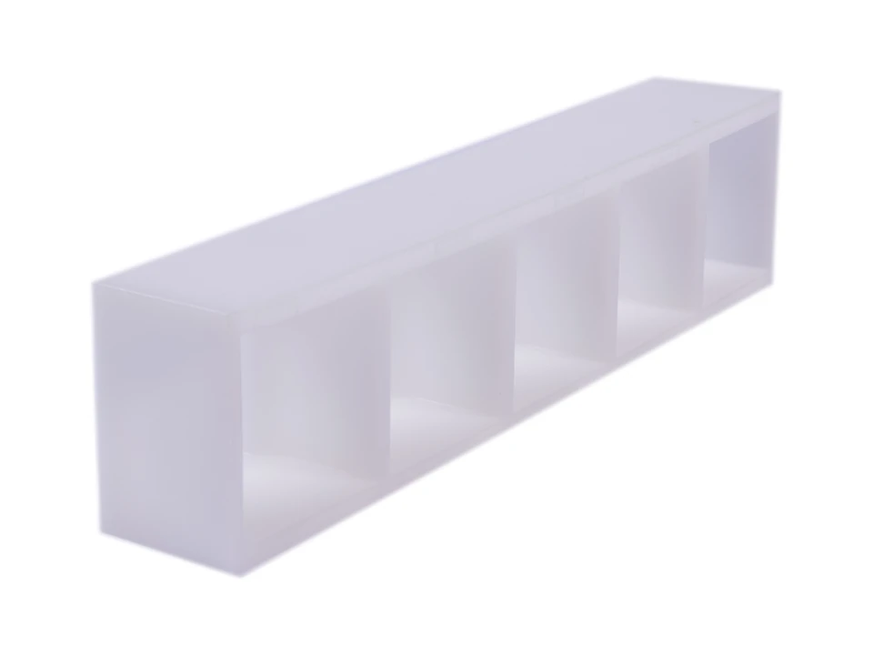
A plastic cage segment for slewing bearings, with a row of pockets separated by molded ribs.
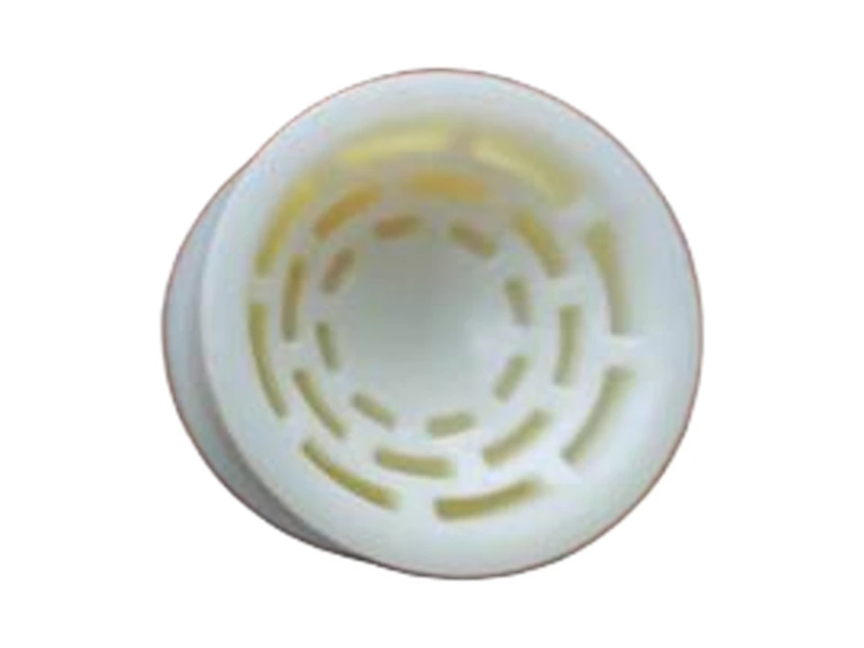
Cup-shaped polymer separators positioned between rolling elements in slewing bearing assemblies. The steel balls in assembly references are separate components.
View componentBearing cage examples from the rail-transit catalog, with drawing-specific pocket spacing and assembly requirements.
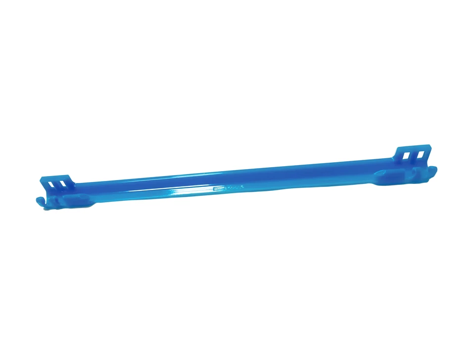
A strip-shaped bearing cage from the rail-transit product catalog. Pocket spacing, locating features and assembly dimensions are reviewed against the selected drawing and revision.
Cooling parts, motor insulation, automotive trim, electronic housings and components with surface-finish requirements.
Cooling impellers for VR headsets, tablets, laptops, CPUs, GPUs and servers, alongside other fan-impeller geometries.
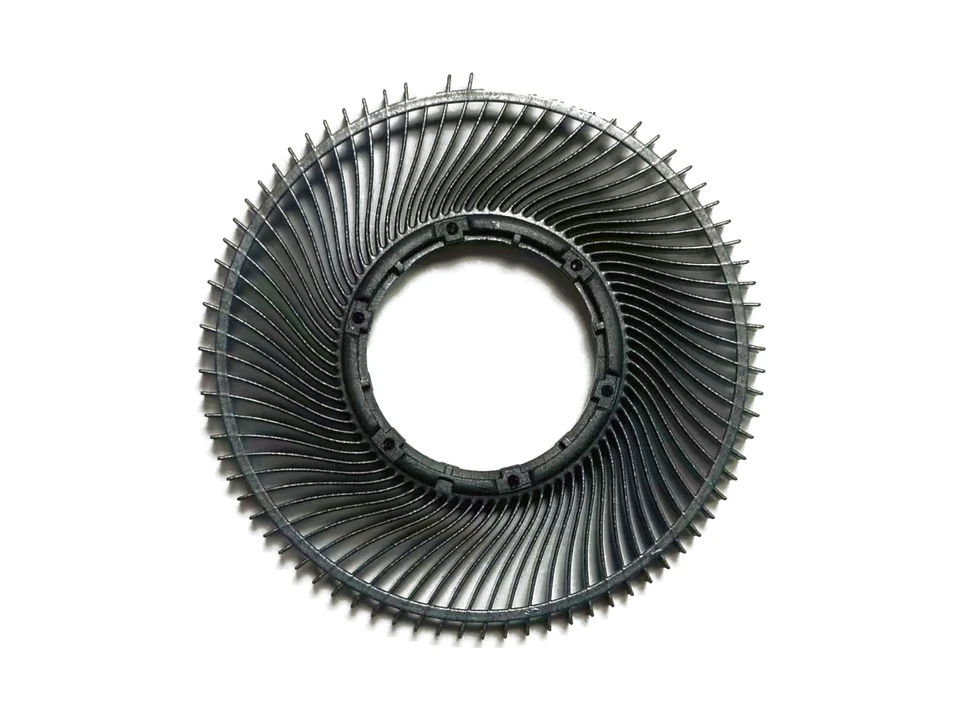
A miniature ring-shaped impeller for VR headset cooling, combining a compact hub and closely arranged blades.
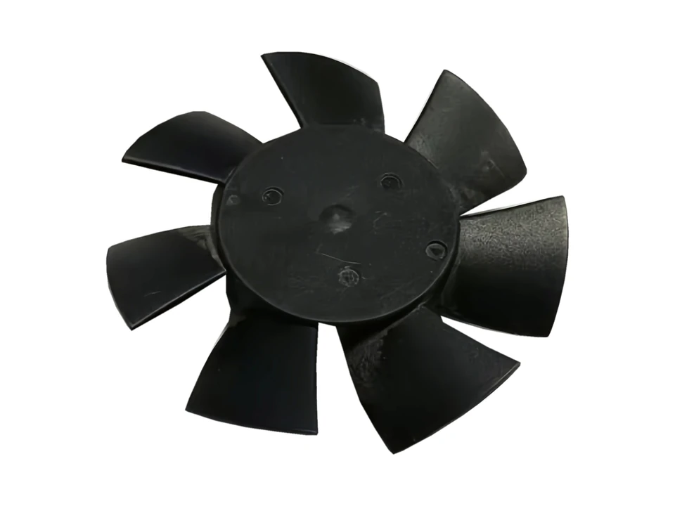
A miniature impeller for tablet cooling fans, with the blade and hub structure packaged for a small fan assembly.
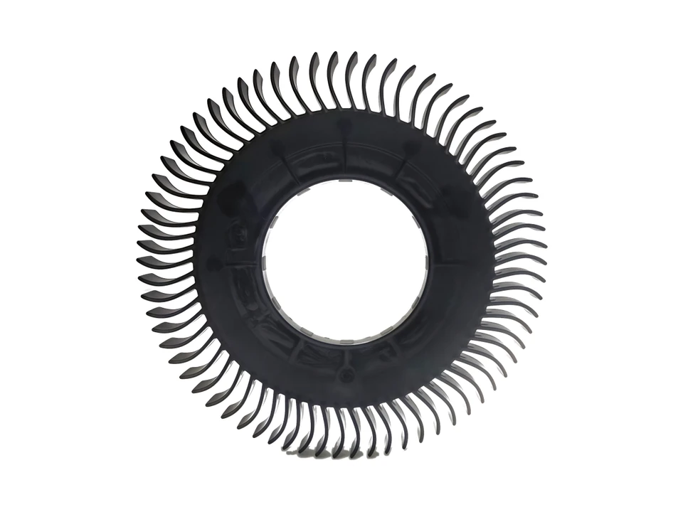
A thin-blade impeller for laptop cooling fans, with a ring-shaped blade arrangement around the hub.
An axial impeller for CPU cooling, with a central hub, curved blades and a surrounding ring.
View component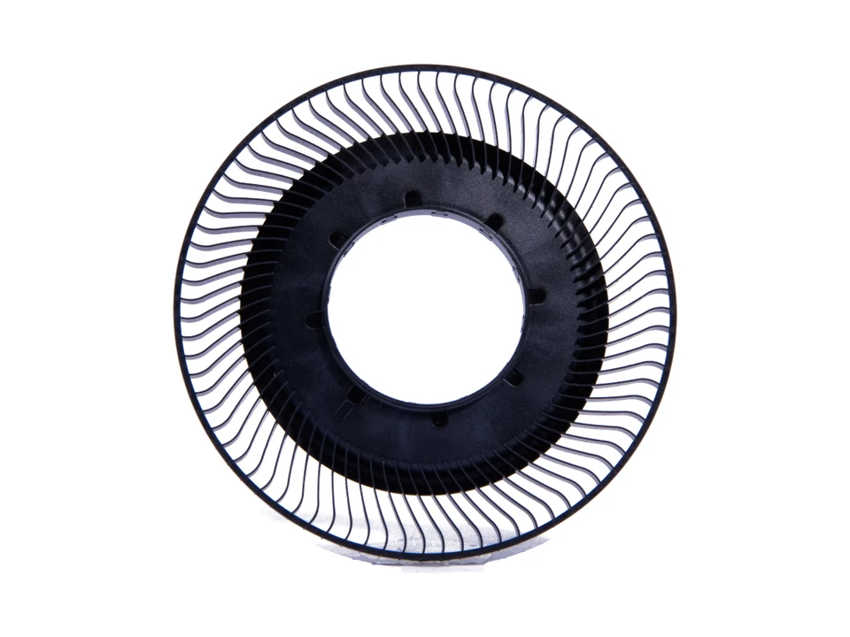
A ring-shaped impeller for GPU cooling, with thin blades arranged around the central hub.
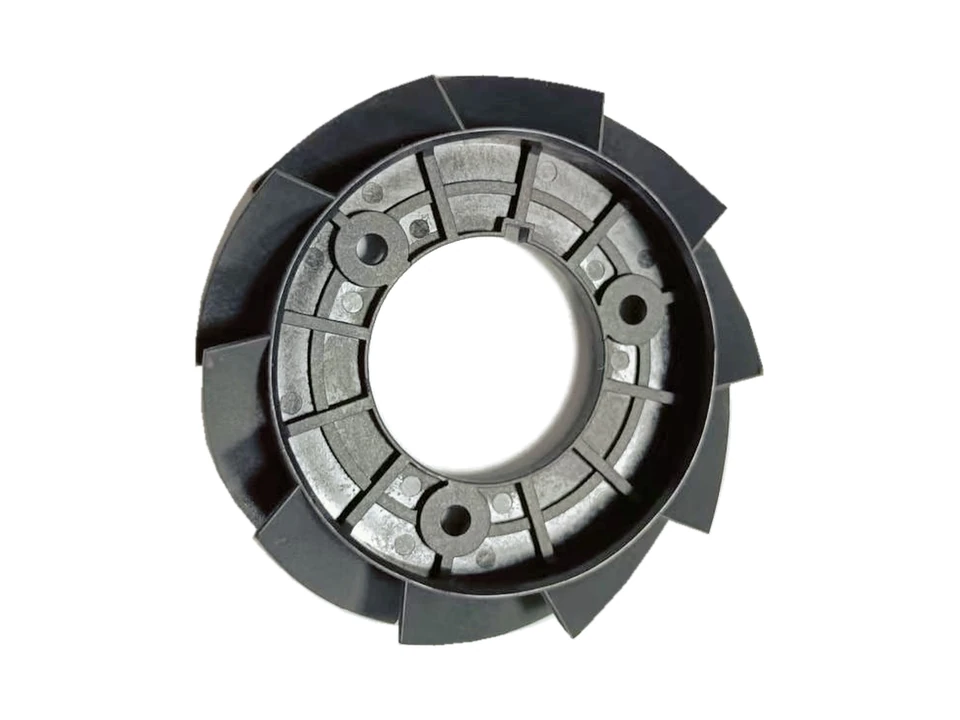
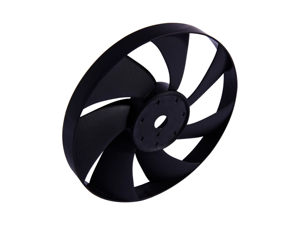
A ring-shaped fan impeller with circumferential blades, a central opening and three mounting holes. Blade geometry, mounting interfaces and molding requirements are reviewed for each application.
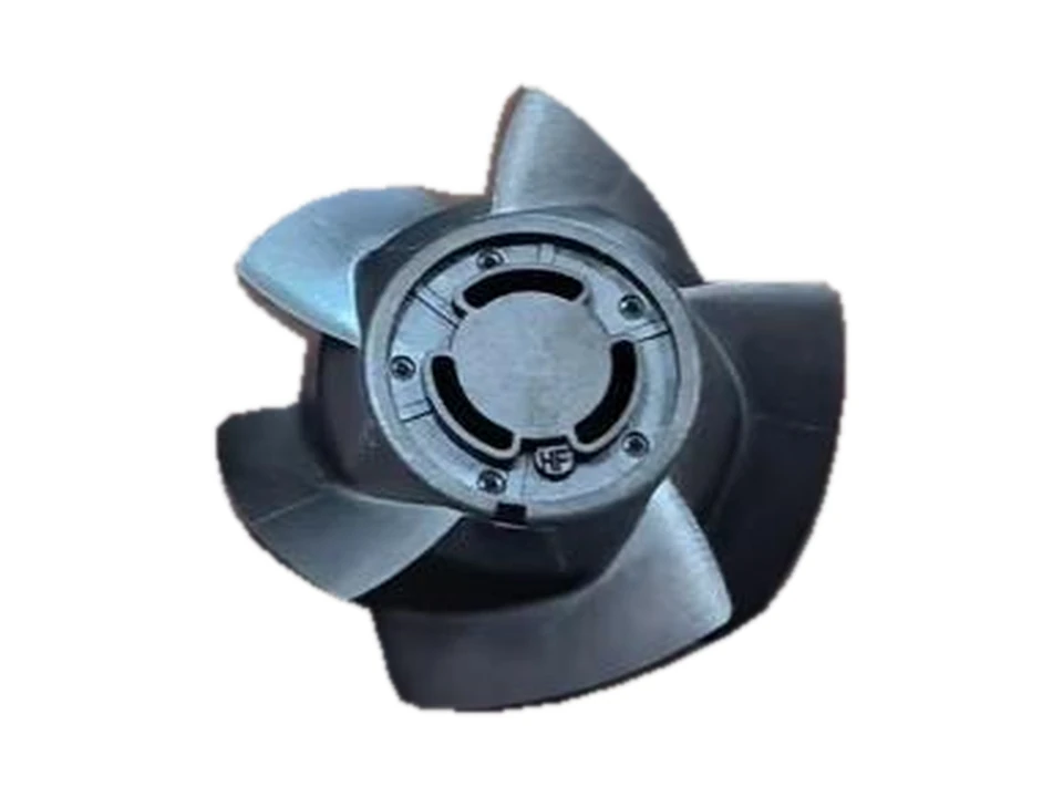
A small server cooling-fan impeller with a compact hub and surrounding blades.
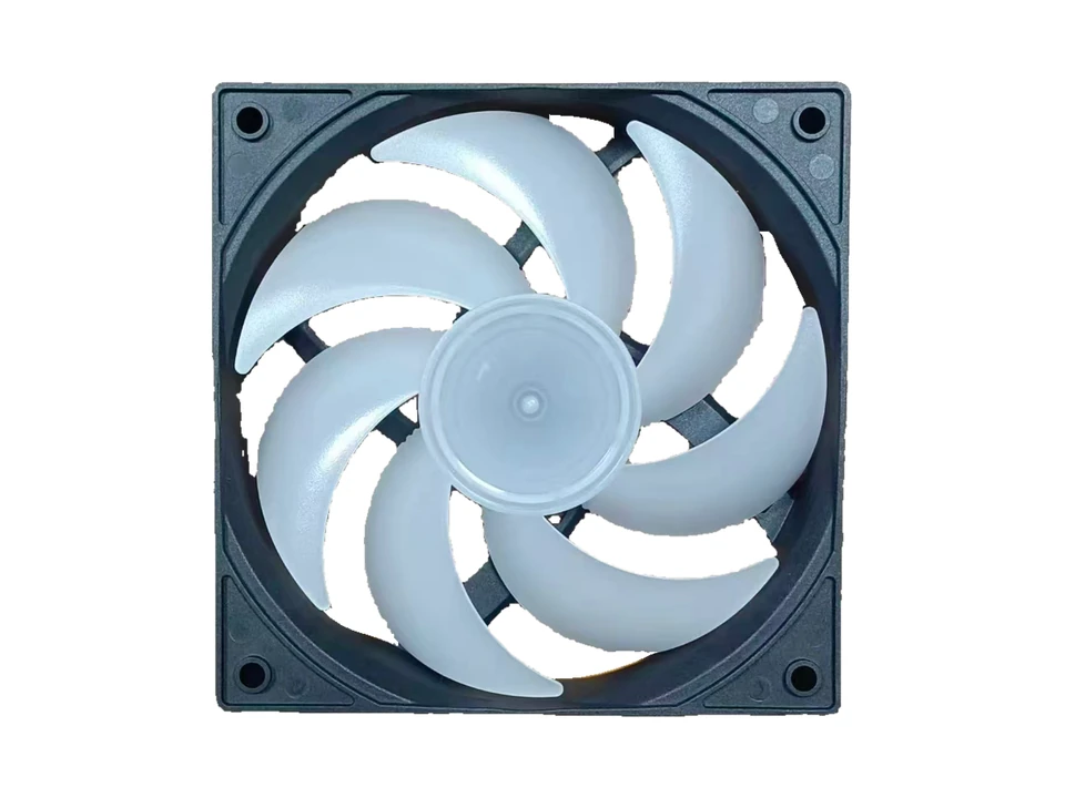
Axial impeller examples with different blade arrangements for larger cooling-fan assemblies. Frames shown with assembled fans are separate structural components.
View componentMetal-and-plastic base structures for notebook and computer cooling fans.
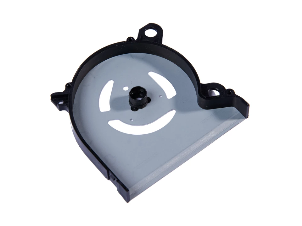
Metal-and-plastic bases for notebook and computer cooling fans, with hub support and mounting features in several base outlines.
View componentMolded insulation structures that fit around motor laminations.
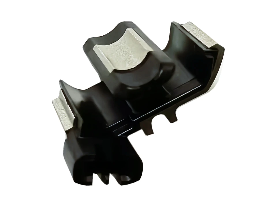
Molded insulation components paired with electrical-steel motor laminations, following the lamination shape and assembly interfaces.
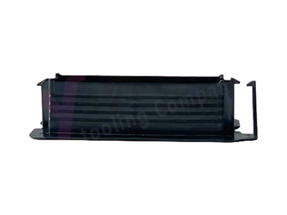
Elongated molded insulation components for motor arrangements, including a transmission-motor insulation example.
View component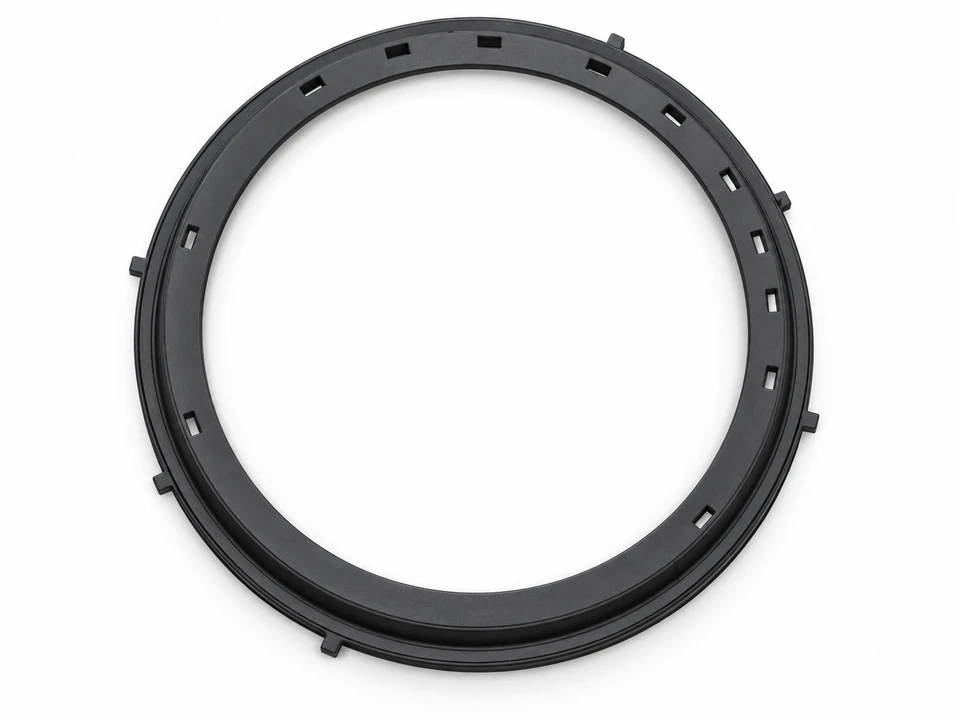
Product rendering
Ring-shaped insulation cover for an in-wheel e-bike motor, with perimeter slots and fixing tabs. Dimensions and material follow the documented design example.
Product rendering
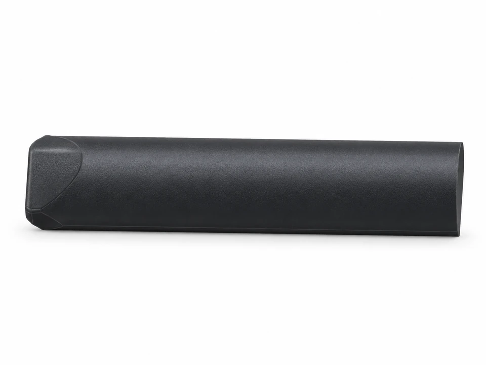
An elongated wedge for an in-wheel e-bike motor. Fit and insulation requirements are reviewed against the part drawing.
Structural housings, frames and metal covers that support and enclose cooling-fan components.
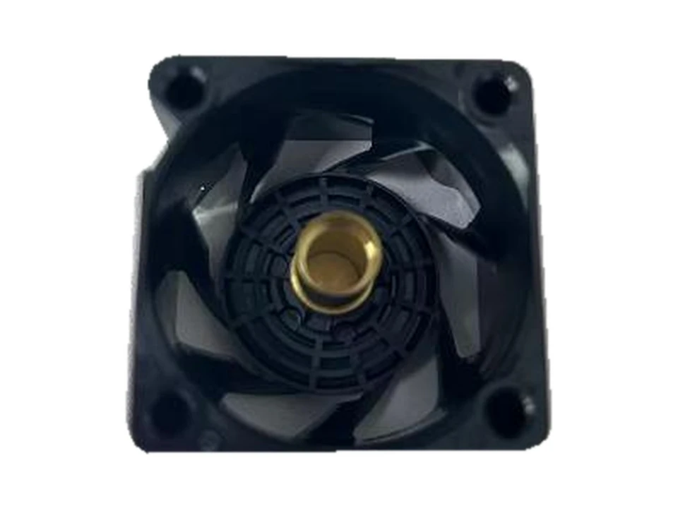
Structural frames and housings for motor-cooling and server fans, with mounting features and interfaces for the fan assembly.
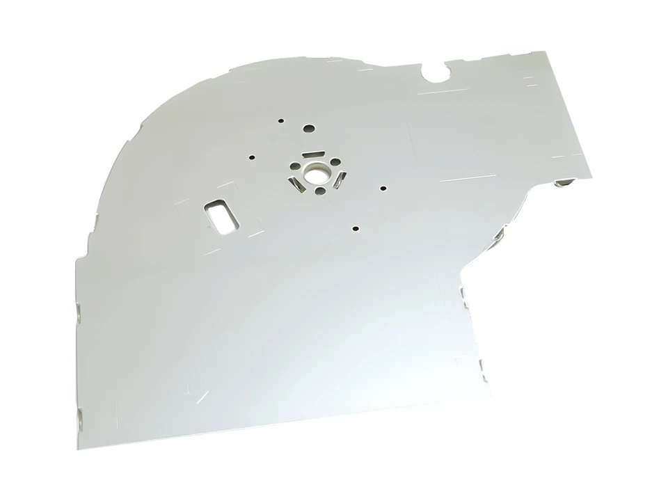
Thin metal covers for computer cooling fans, with mounting holes and a shaped perimeter that mates with the fan base.
Lamination stacks, housings, shafts and airflow structures associated with motor assemblies.
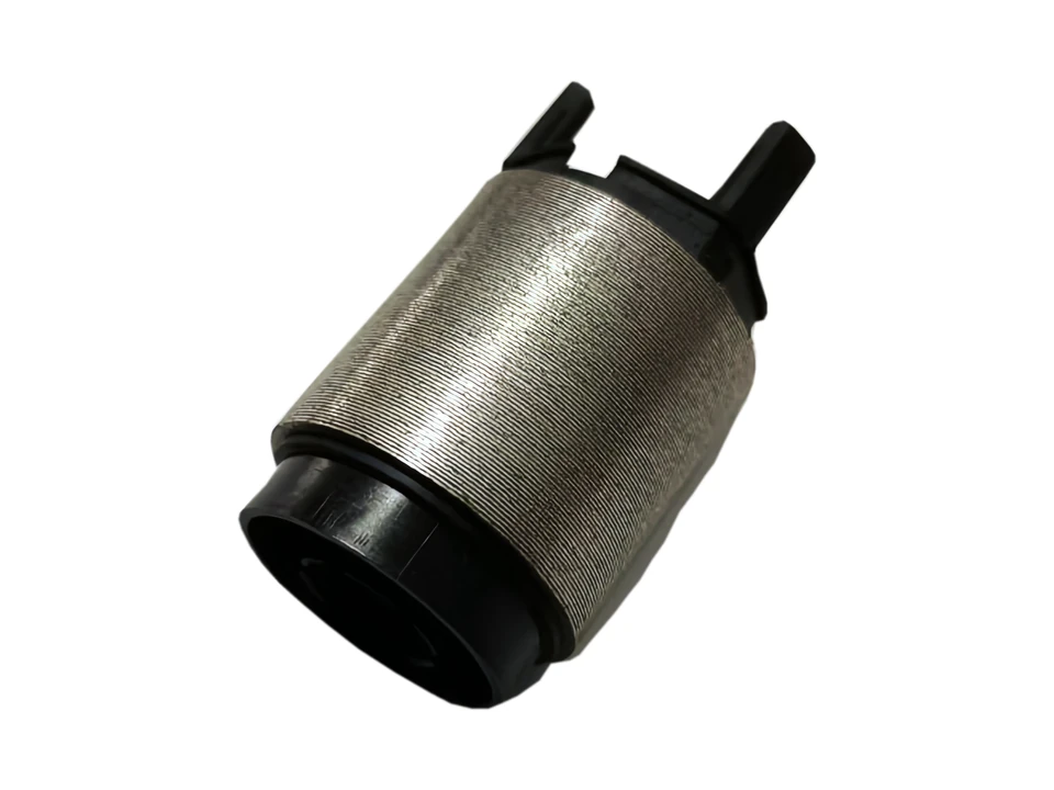
Cylindrical electrical-steel lamination stacks combined with molded insulation. The insert and molding scope is reviewed for each assembly.
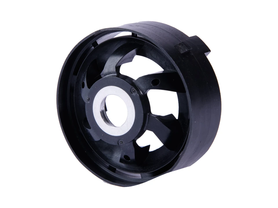
A related family of housing, diffuser and shaft components used around miniature-motor assemblies. Each component retains its own geometry and supply scope.
View component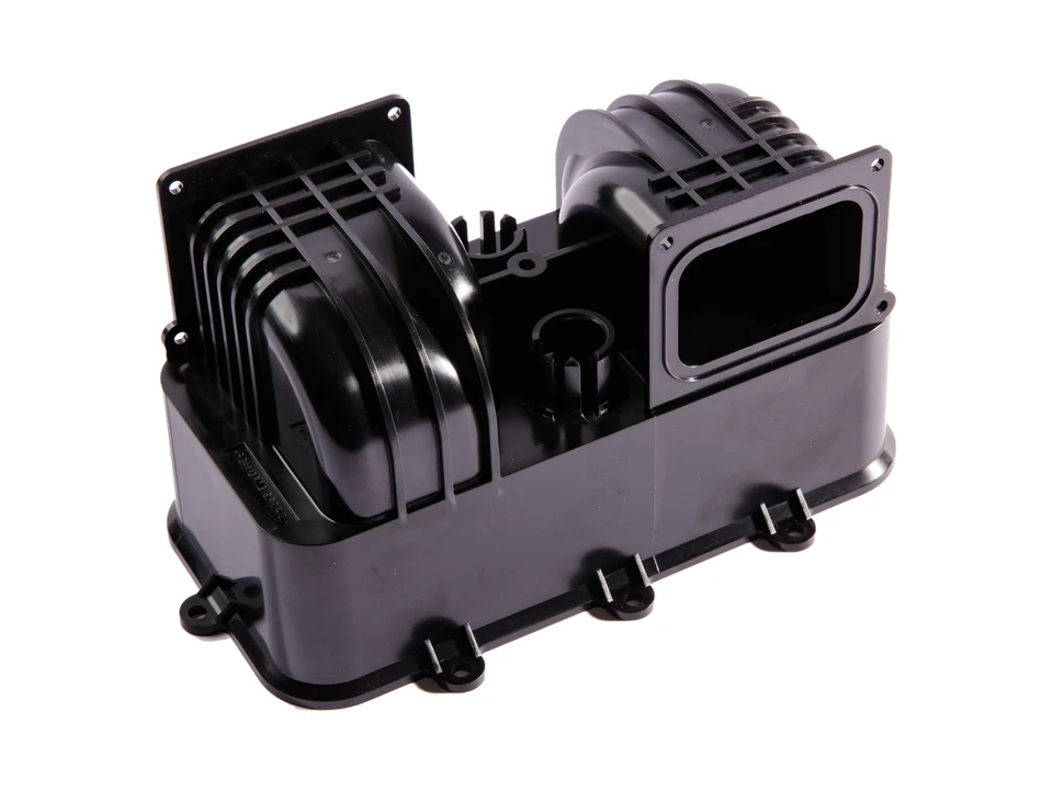
Outlet, bracket and body components arranged around the hand-dryer motor airflow path, with individual parts and assembly interfaces.
View componentInterior and exterior trim, panels, buttons, lighting structures and mirror-related components.
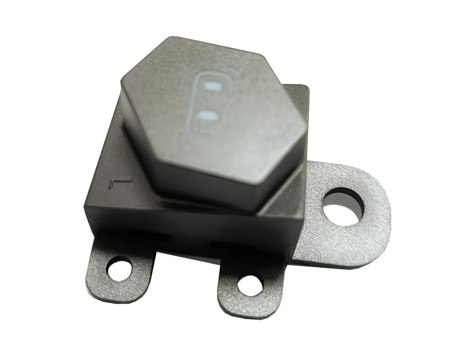
Documented examples of molded buttons and switch trim for automotive interiors, with functional openings and assembly features.
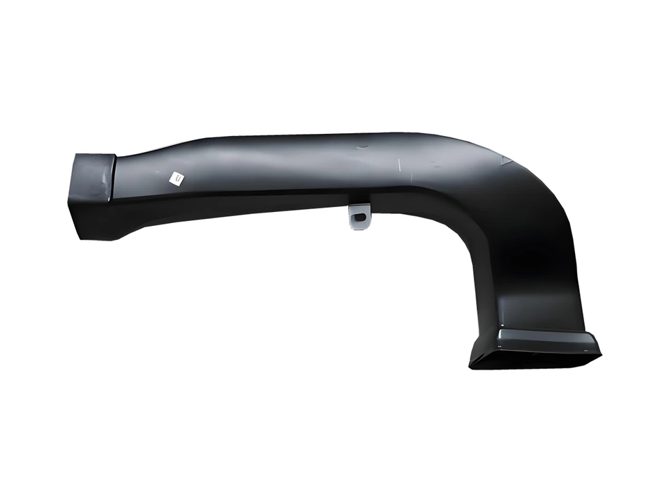
Documented housing, curved tubular and mounting-part examples for automotive exterior assemblies.
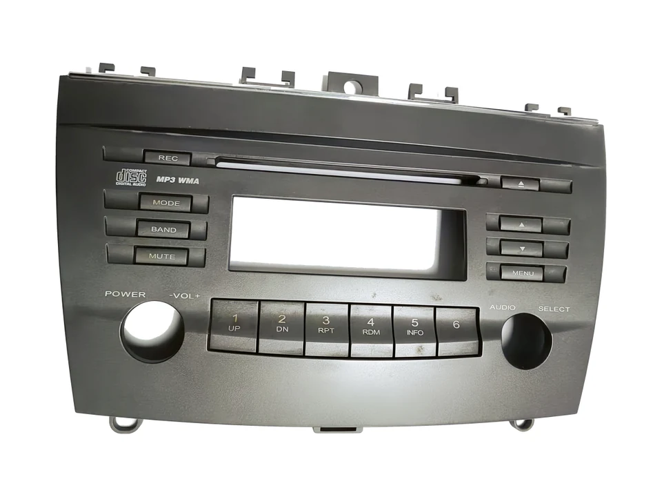
Documented center-console panel and bezel examples with display windows, button openings and mounting features.
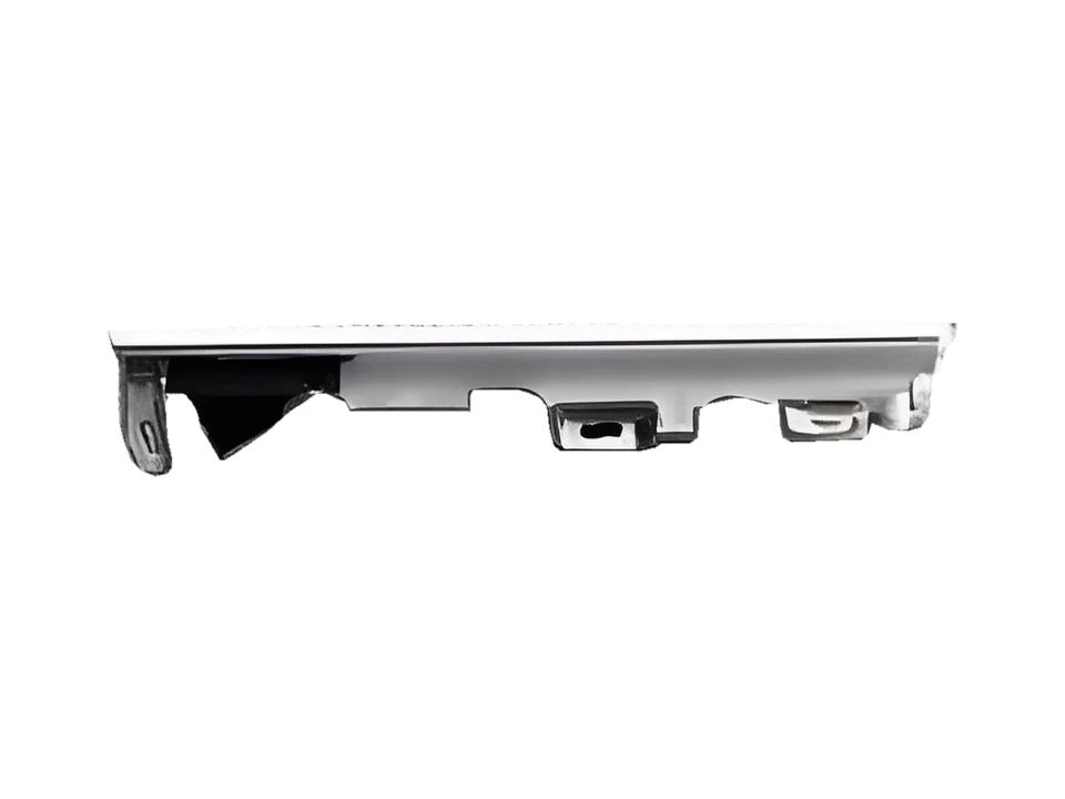
Documented elongated structural and connection parts for automotive ambient-light assemblies. Optical and electronic components have a separate supply scope.
View component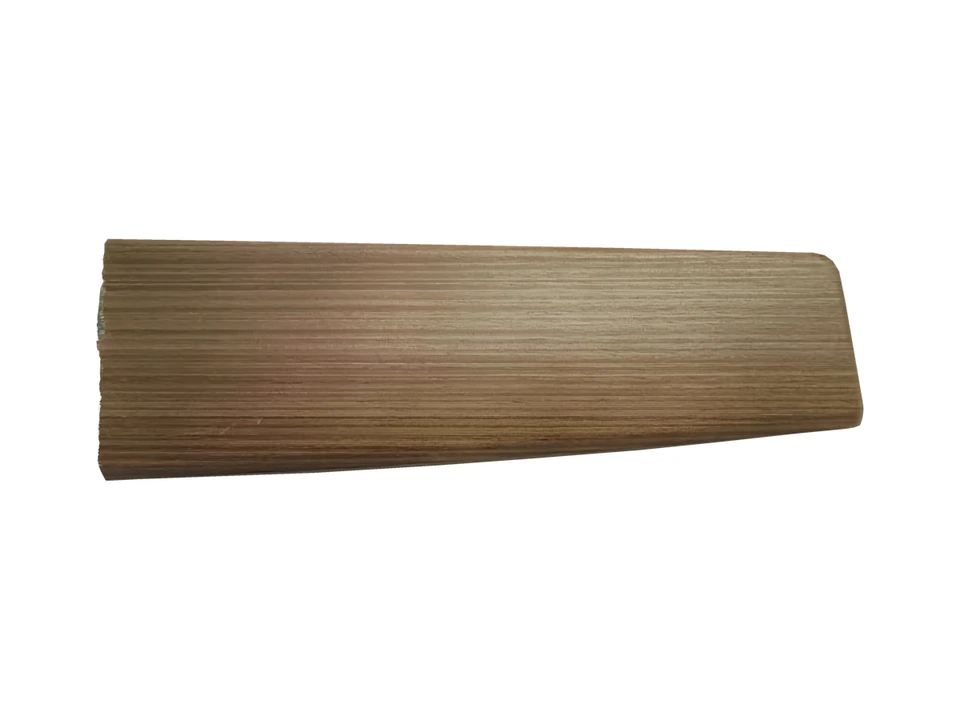
Documented door trim panels and decorative strips with shaped surfaces and attachment features.
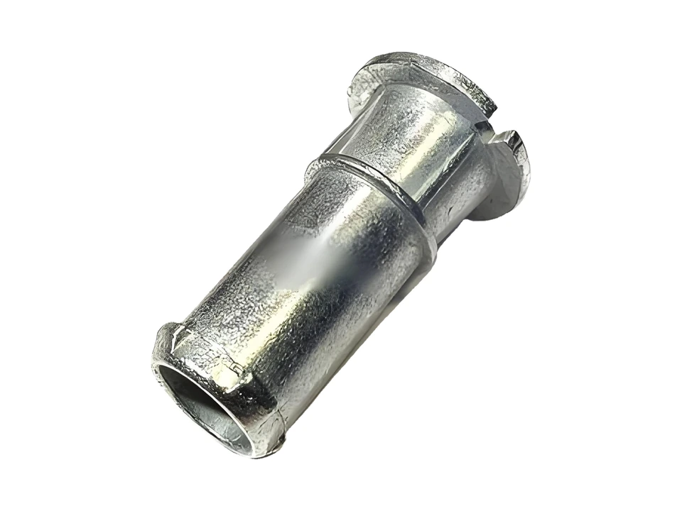
Documented pivot and shaft component examples associated with automotive mirror assemblies.
View component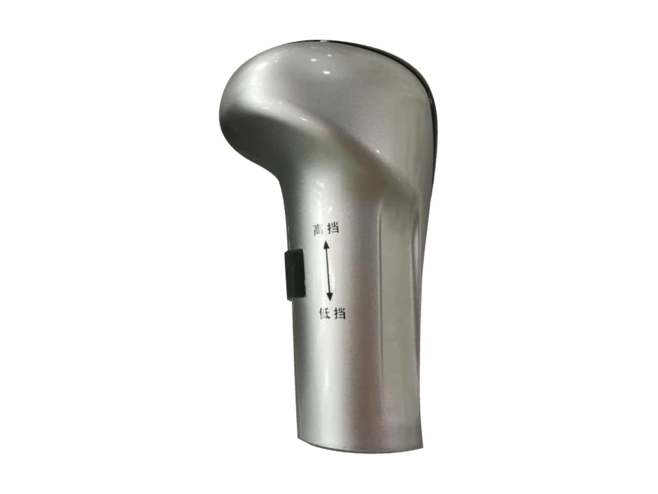
Exterior trim for automotive gear selectors. Define the molded-part and surface-finish scope from the assembly interfaces, color and marking requirements.
View component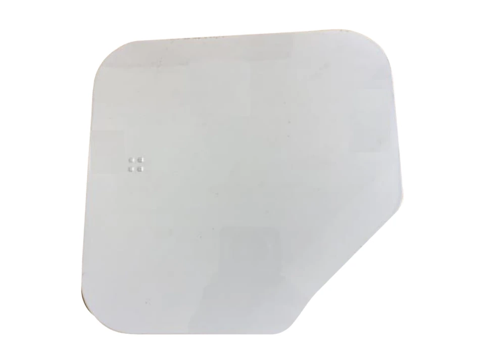
Exterior trim for automotive fuel-filler covers. Check the profile, assembly fit and finish requirements; specify the substrate and coating system for each project.
View componentConnection parts, covers and small molded structures for thermal-management and equipment assemblies.
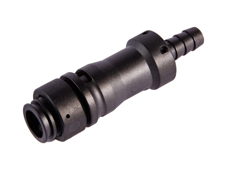
Tubular connection parts documented for cold-plate assemblies. The component scope covers the fluid connection, with mating interfaces reviewed against the assembly design.
View component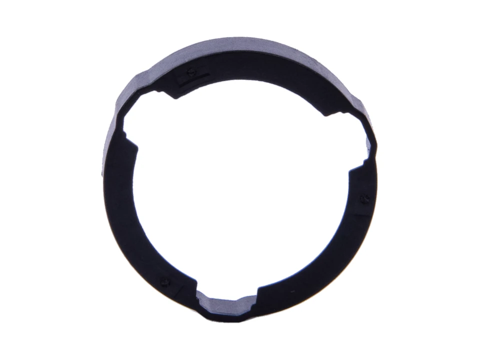
Ring-shaped cover components documented for a battery-cover application. The cover geometry and mating features are reviewed for the specified assembly.
View component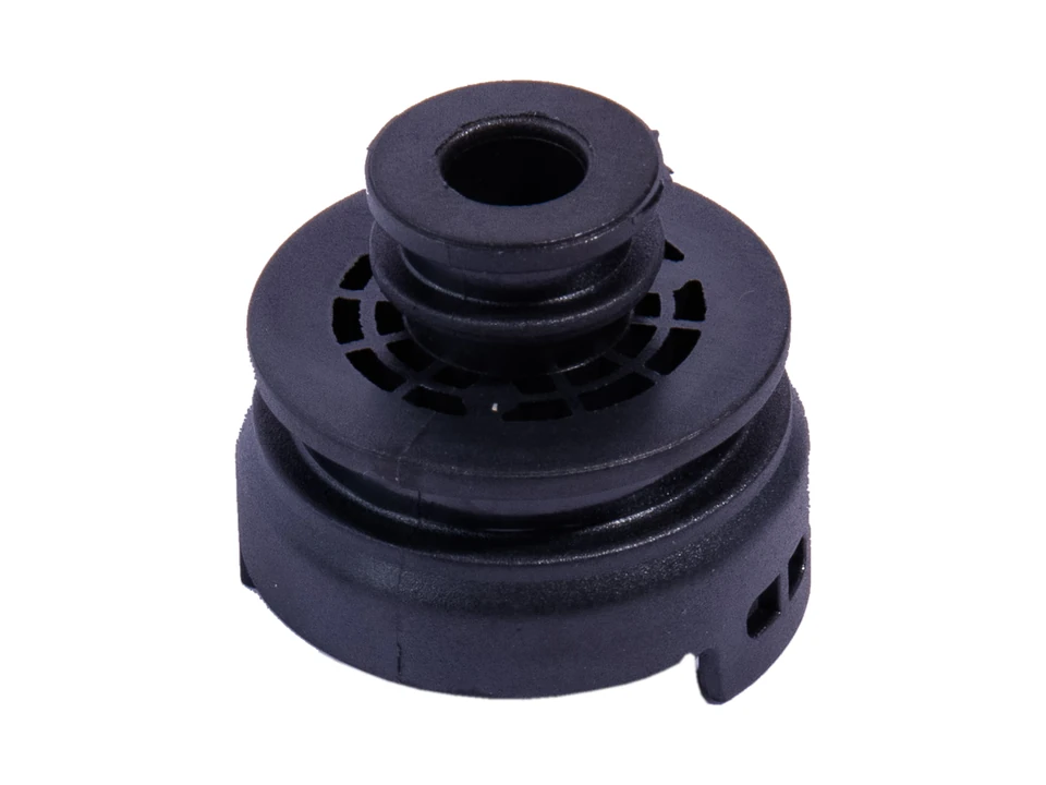
Tubular, flanged and small structural components documented in PPS. Resin grade and performance requirements are specified for each part.
Phone and headphone housings, display covers, antenna housings and key exterior components.
Detail photograph
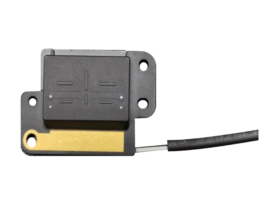
Exterior housings for antenna units. Review the housing profile, mounting points and cable exit with the drawing to define molding and finish requirements.
View component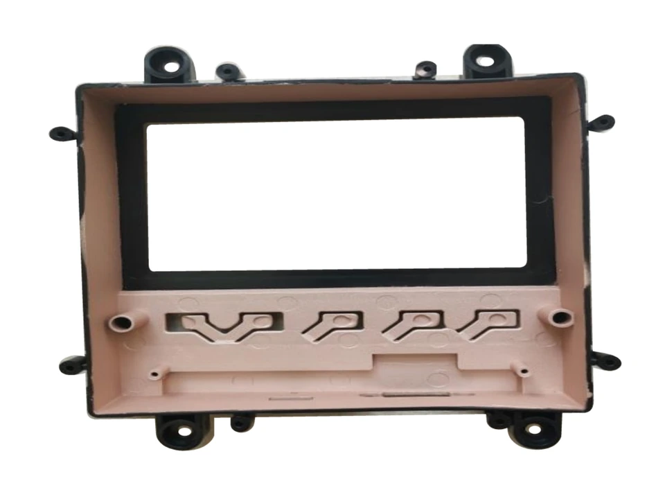
Detail photograph
Covers and bezels around electronic displays. Check the window dimensions, fixing positions and inner and outer finish requirements against the screen and mating parts.
View component
Housings and exterior components for keys. Review the shell fit, button openings and marking requirements; define electronics and complete-device assembly separately.
View component
Detail photograph
Exterior phone housings with openings around cameras and functional interfaces. Review the shell fit, opening positions and finish requirements when defining the mold and molded part.
View component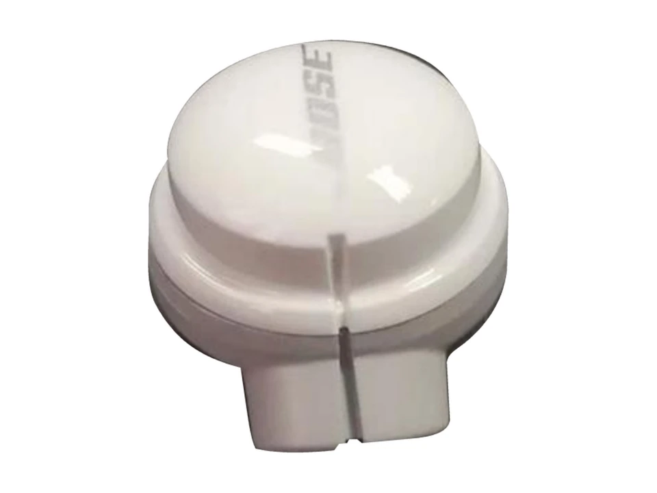
Headphone housings and exterior structural parts. Review the shell fit, connection features and surface requirements to define the manufacturing scope for each component.
View componentCoating and appearance finishing for cosmetic containers and metal exterior components. Component manufacture and surface processing have separate supply scopes.
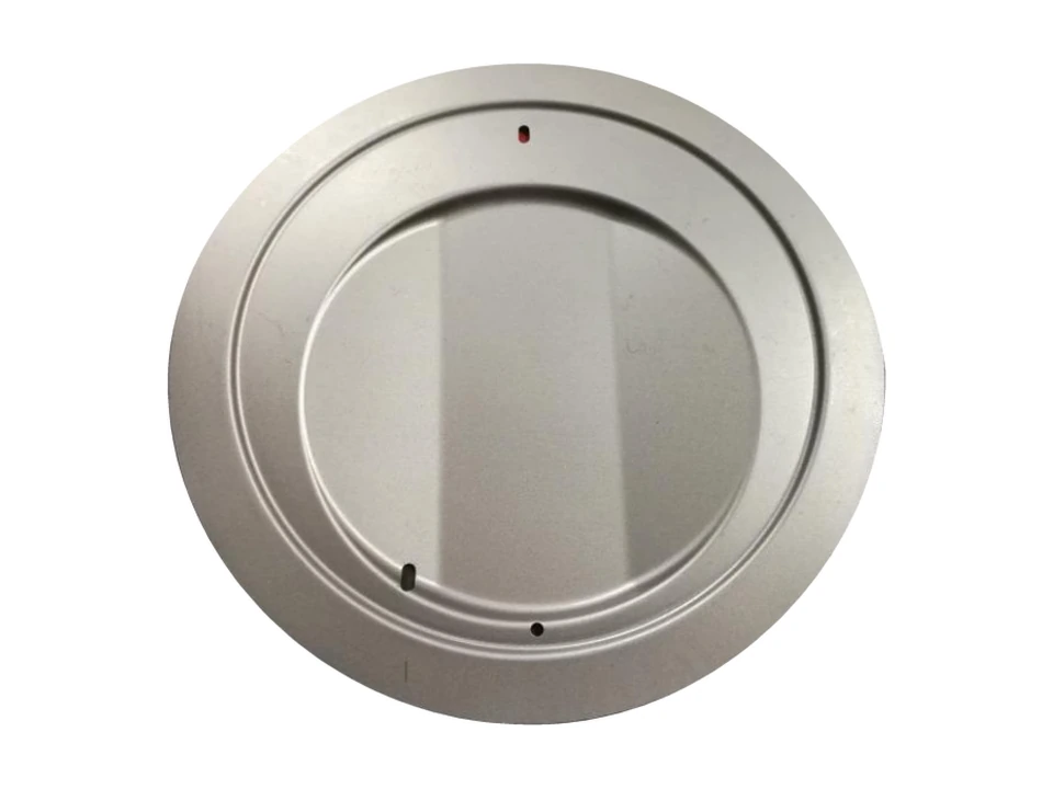
Coating and finishing for metal exterior components used in electronic products. Define the processing scope and inspection requirements from the substrate, visible surfaces and assembly positions.
View componentSurface finishing for cosmetic containers. Review the substrate, color and coating requirements; define container molding and surface processing as separate supply scopes.
View componentSamples and product families support custom projects. Specifications, materials, inspection requirements and supply scope are assessed against your drawings.
Geometry, material and inspection requirements shape the tooling and molding approach.
Share your drawing revision, quantities and key requirements so we can discuss the project.