
Gearboxes.
These gearbox samples show the housing outline, fixing points and internal gear arrangements. Review the housing and gear drawings together to define the required molded parts and mating interfaces. Purchased components and assembly responsibilities are agreed as separate parts of the project scope.
Discuss your component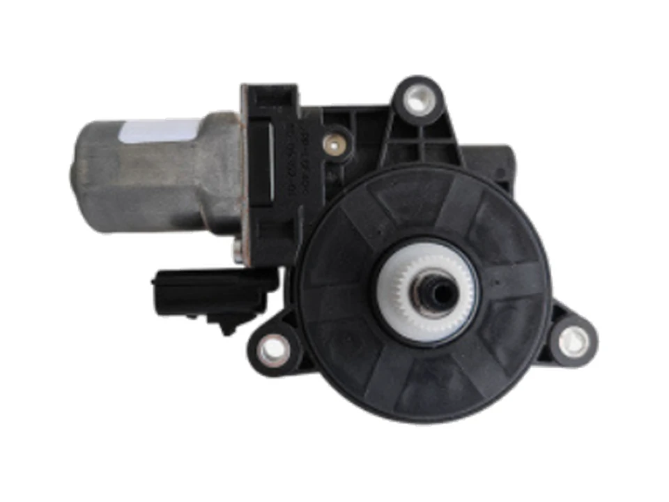
More structures in this family
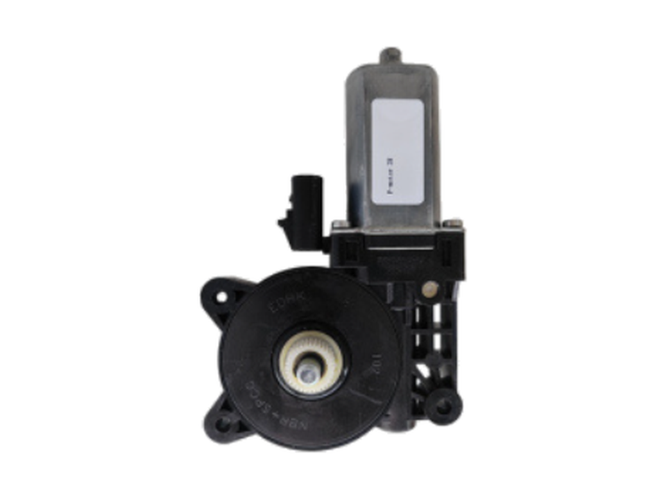
Gearbox assembly — view A
Gearbox sample showing the housing outline, mounting structure and output interface.
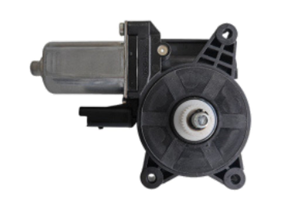
Gearbox assembly — view B
Assembly view showing the motor position, three mounting points and the gearbox interface.
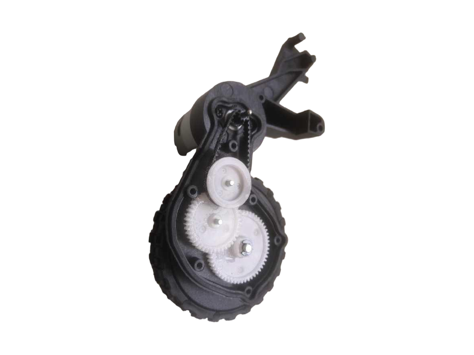
Open-cover gear arrangement
The open housing shows the gear arrangement and engagement.
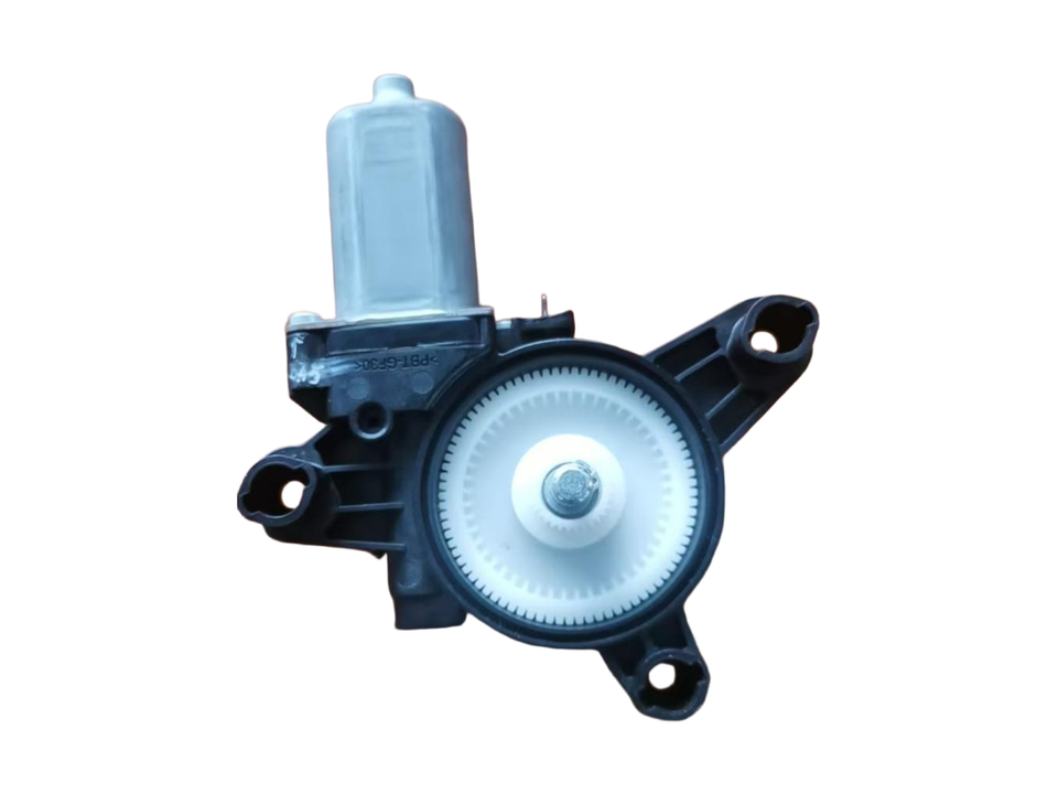
Gear and output-side arrangement
The assembly view shows the large gear and output interface.
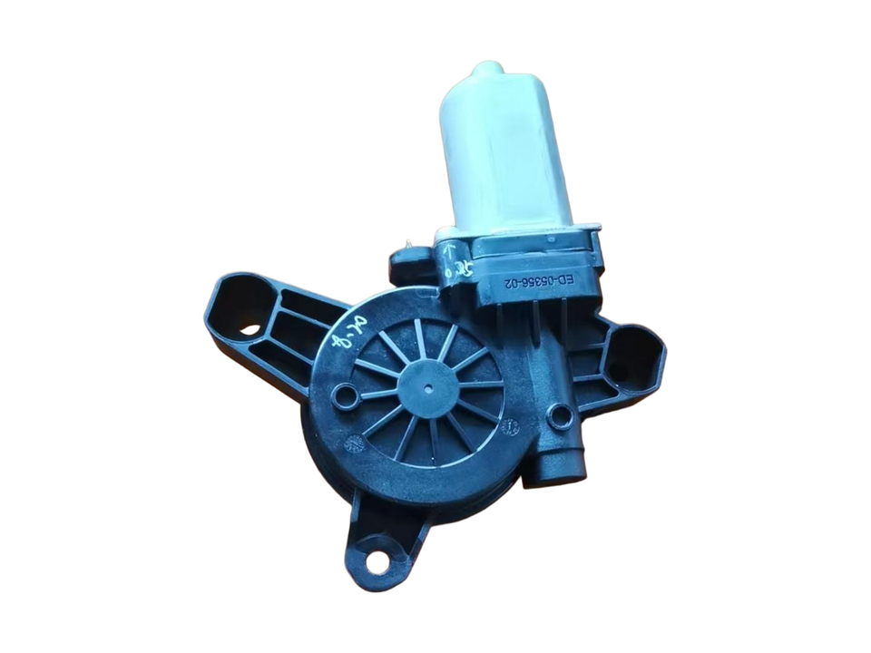
Housing outer-side arrangement
The outer housing shows radial ribs, mounting arms and the motor connection area.
Start the review with specific requirements.
Provide the part drawing and revision, material requirements, project quantities and critical inspection points. For metal inserts, specify responsibility for conductor or insert supply.
- Geometry & interfaces
- Mating, fixing and assembly interfaces
- Material & molding
- Material requirements, insert boundaries and tooling scope
- Inspection & delivery
- Critical checks, quantities and project schedule
Inputs for a component review
Provide the part drawing and revision, material requirements, sample and project quantities, and the mating interfaces or inspection points that matter for your part. Where metal inserts are involved, include the insert drawing and state who will supply them.
Explore application requirementsComponent directions in this family
Start with your drawing and requirements.
Share your drawing revision, quantities and key requirements so we can discuss the project.