
EV busbar connectors.
This EV busbar connector sample has three square threaded inserts separated by raised walls in the molded body. Review the conductor interfaces, mounting points and insulation boundaries with your drawings. Material, insert supply and electrical acceptance criteria are defined for each project.
Discuss your component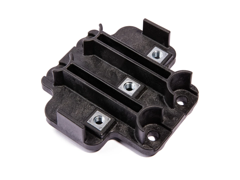
Component details & example specifications
Photographs illustrate the product family. Documented variants are listed separately below. Tolerances, materials and acceptance criteria are reviewed against your drawings.
| Property | Value / description |
|---|---|
| Dimensions | 90 × 90 × 24.5 mm |
| Weight | 63 g |
Plan the connection and the molded body together.
The metal interface and surrounding molded features need to fit the same assembly. A useful review starts with the conductor drawing, fixing points and the boundaries of the insulating body.
- Metal interfaces
- The sample shows three square threaded inserts. Define the interfaces and insert positioning from the drawing for your version.
- Molded partitions
- Raised walls divide the connection areas. Identify the required molding boundaries and surfaces that must remain exposed.
- Assembly envelope
- Review the outside profile, mounting positions and mating components as one set of interfaces.
Bring the details that define your part.
Clear drawings and requirements help define the tooling, molding and inspection work.
- Part and insert drawings
- Provide the drawing revision, conductor or insert geometry, fixing details and the intended assembly.
- Material and insulation criteria
- Specify the material requirement, application conditions and electrical inspection criteria for your project.
- Supply and inspection scope
- Clarify who supplies inserts, the required quantities and the dimensional and visual checks for sample approval.
Questions before starting a project
Can the connection layout be changed?
A different layout starts a drawing-specific tooling and molding review. Share the mating interfaces and package constraints so the requested geometry can be assessed.
Which electrical requirements should I include?
Include the required voltage and current, operating environment, insulation criteria and your validation method. These inputs help define the material and design review for your project.
Who supplies the metal inserts?
Insert supply, incoming checks and molding responsibilities are agreed as part of the project scope. Include your preferred supply arrangement with the inquiry.
Before you request a quote
- Provide the plastic-body and insert drawings with the same revision and mating-interface information.
- Mark contact surfaces that must remain exposed and specify the material and electrical acceptance criteria.
- State who supplies the inserts, the required quantities and the checks needed for sample approval.
Start with your drawing and requirements.
Share your drawing revision, quantities and key requirements so we can discuss the project.