
Precision molds. Injection and insert molding.
Connect precision tooling, injection molding and insert molding around your part drawings and operating requirements. Review geometry, materials, critical dimensions and inspection criteria together at the start of the project.

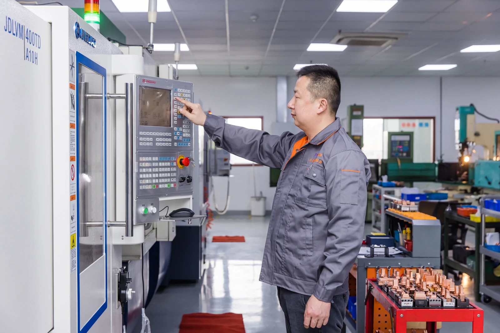
Tooling starts with the part.
Review the part geometry, material shrinkage, release direction and mating interfaces together. Use the critical features to guide the mold approach, and define the trial, sample approval and delivery requirements.
- Part requirements
- Drawing revision, datums, critical dimensions, cosmetic surfaces and assembly interfaces.
- Mold use
- Tooling for part supply or delivery to another site, with machine interfaces and acceptance requirements agreed for the project.
- Trial and approval
- Sample review, inspection records, tooling documentation and delivery responsibilities.
Injection molding for functional components.
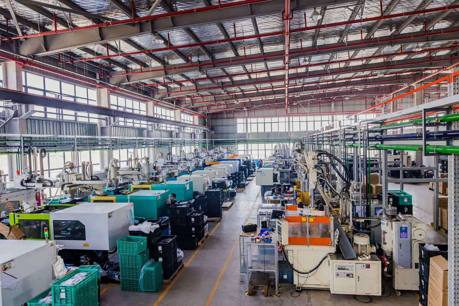
Start with the resin requirements, critical dimensions and cosmetic surfaces to define molding and inspection conditions. Gears, busbar insulation components, bearing cages and electronic cooling parts each have different mating interfaces and operating environments.
- Geometry and fit
- Review wall sections, ribs, openings, mounting points and mating components.
- Material and use
- Provide the specified resin grade or the application requirements that need evaluation.
- Inspection and acceptance
- Agree critical features, inspection methods, appearance criteria and sample approval.
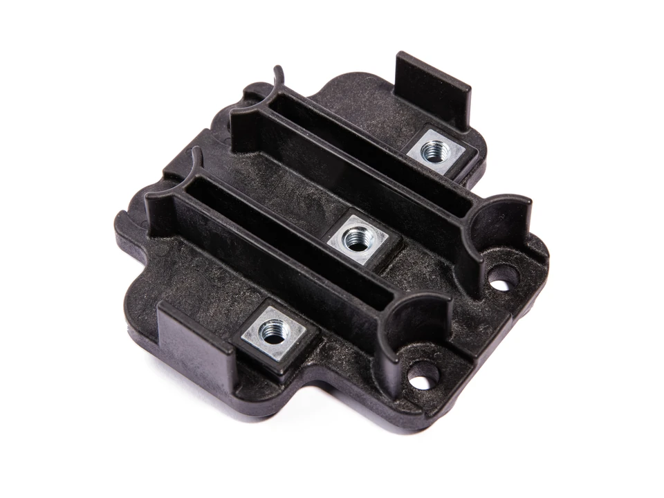
Plan the insert and molded body together.
For busbar insulation components and other insert-molded parts, the exposed interfaces, molded boundaries and insert position need a shared definition. Discuss the insert drawing, material, surface condition and loading requirements alongside the plastic body.
- Insert supply
- Define the insert specifications, preparation requirements and supply responsibilities.
- Position and interfaces
- Identify locating features, retention requirements, exposed surfaces and mating interfaces.
- Validation requirements
- Provide the applicable dimensional, mechanical or electrical criteria for the project.
A clear path from requirements to delivery.
Use one set of project requirements to connect tooling, molding and inspection discussions.
Review the requirements
Align the drawing revision, application, material requirements and expected quantities.
Define tooling and molding
Discuss the part structure, mold use, insert responsibilities and critical features.
Agree sample approval
Set the sample review, inspection methods and acceptance criteria.
Plan the delivery
Confirm tooling or part supply, documentation, packaging and target schedule.
Tooling, molded parts or both?
Tell us what you need to receive and where it will be used. Insert sourcing, metal processing, finishing, assembly and inspection responsibilities should be agreed individually for the project.
Read the supply-scope guideExplore quality and inspectionStart with your drawing and requirements.
Share your drawing revision, quantities and key requirements so we can discuss the project.